Last Updated: Aug 26, 2025
Author: Dave Overacker
Edited By: Duc Bui
Objective
Exxact Corporation is implementing a revised packaging method using Instapak foam to assist in shipping Phanteks-based workstations. This foam solution provides superior protection during transit but requires partial disassembly for removal.
This document outlines the step-by-step procedure to remove the Instapak foam and reinstall components safely.
Affected Systems:
Valence XL Workstations using Phantek case
How to Identify your Workstation Case Model
Tools Required
- Phillips screwdriver
- Flat stable surface
Important Notes
- The fan bracket must be temporarily removed to extract the Instapak foam.
- Fan cables may become unplugged during foam expansion. We are labeling fan cables as “A” and “B” to simplify reconnection.
- Ensure power connectors are fully seated after removing the foam.
Instructional Video
Step-by-Step Instructions
1. Preparation
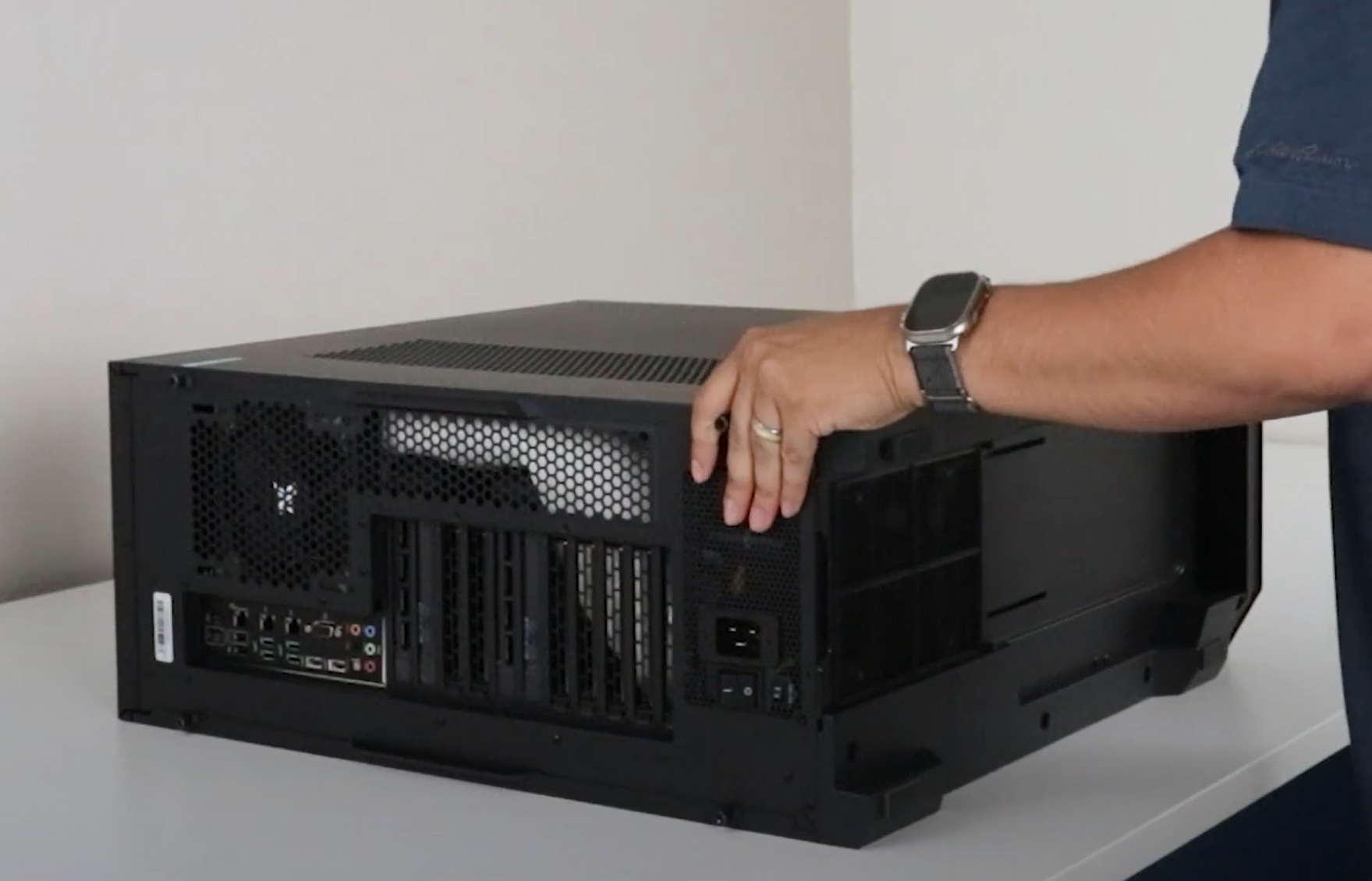
- Place the system flat on its back side on a stable surface.
- Prepare a Phillips screwdriver.
2. Remove the Side Panel
- Loosen the two screws on the rear of the side panel.
- Pull or lift the panel using the rear handle.
- Once the front is free, completely remove the entire panel.
3. Remove the Fan Bracket
- Locate and remove four screws securing the fan bracket (2 at the top and 2 at the bottom).
- Push the bracket towards the top until the bottom is free.
- Lift the bottom out of the chassis and then pull the bracket out.
- If the fan cable is still attached, let the bracket hang outside the chassis carefully.
4. Remove the Instapak Foam
- Grab and pull the foam out, you may need to wiggle and firmly pull if it is stuck.
- Inspect power cables and connectors to ensure nothing has loosened during shipment.
5. Reinstall the Fan Bracket
- Insert the top of the bracket into position first.
- Once the top is in and the bottom clears the chassis, push the bottom into the case and move the bracket down to align the screw holes
- Align the holes and reinstall all 4 screws.
- Reconnect any disconnected fan cables, matching labels “A” and “B” as necessary if the cables are labelled.
- Different configurations may include labelled cables.
6. Reinstall the Side Panel
- Align the side panel approximately 1 inch away from the front edge of the chassis.
- Lay panel flush on the chassis and push towards the front
- Once in, tighten the rear thumbscrews to secure the panel.
- Remove any stickers from the chassis.
Best Practices
- Use Electro Static Discharge (ESD) bands or ground yourself to prevent static electricity damage
- Take photos or label each cable before disconnecting cables to make reconnection easier
Comments
0 comments
Please sign in to leave a comment.